The first thing I saw when I opened the bags of kit were the SMD components - which scared me somewhat - having done a lot of soldering before but never with surface mount. Still, the assembly manual included some good advice, and I wasn't too nervous about soldering them.
 |
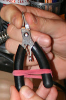
| Look! No Hands! |
Then I set off. The advice on soldering SMD in the manual is very well written, and I had no issues when I followed it pretty much to the letter, despite not having decent tweezers, and having to find a couple of errant resistors which had pinged across the desk on a few occasions!
Firstly, a couple of tips. As you can see in the picture to the right, I tightened an elastic band around my pliers to hold them together - this makes holding things in them a hands free operation, and make life a lot easier! I also pre-soldered one of the two pads for all of the SMD devices, which meant I could easily identify them and could spend more time concentrating on the fiddly bits.
 |
| Using the IDC connector to keep pins aligned |
All in all, the assembly went pretty smoothly, and (as I didn't have my multimeter to hand) I decided to risk it and went ahead and powered the board up straight away - without testing voltages, etc - I wouldn't recommend this, but I got lucky and it worked first time - I only checked with the button demo, I'll be playing with it more over the next few weeks / months.
 |
| The completed board, wired for the button test |
 |
| The button test running on the pi (sorry for the quality of this one!) |
No comments:
Post a Comment